Common p&id symbols used in developing instrumentation diagrams Process flow diagram symbols Flow sensor schematic symbol
Common P&ID symbols used in Developing Instrumentation Diagrams
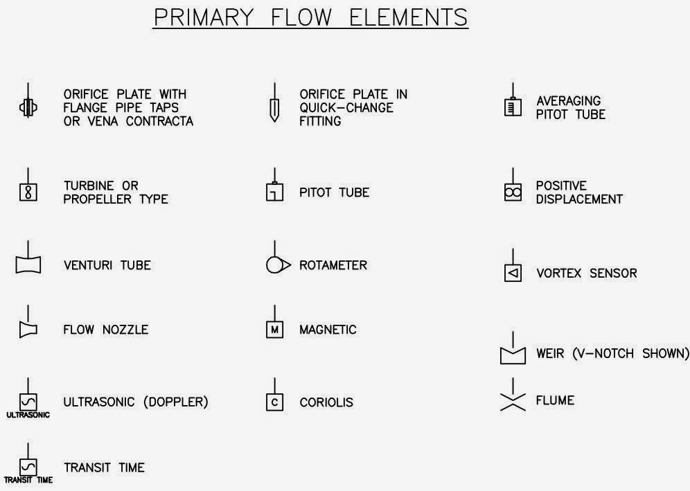
Its all about instrumentation and automation: primary flow elements Electric circuit diagram for the flow sensor and feedback flow control Circuit diagram of water flow sensor namely yf-s401.
Water flow sensor interfacing with arduino – measure flow rate
Flow sensor schematic symbolDiagram pfd indicator instrument Flow meter symbolH2s.
The flow sensor signal conditioning circuit.Air flow sensor : working, types, interfacing & its applications Hydraulic flow meter symbolFlow sensor circuit diagram.
![Current Sensor Schematic Symbol](https://i.pinimg.com/originals/9e/95/68/9e956873a5ee15c59dd2d5242ea70291.png)
Instrumentation piping flow boiler pid diagrams developing meter sensors simbologia mechanical overview symbole ids proses symbology schéma symboles
Current sensor schematic symbolSensor schematic symbol Flow sensor schematic symbolPressure sensor hydraulic symbol.
Mass flow meter symbolAn overview of the common symbols of control signals, piping Meter instrumentation piping symbology sensors diagrams interpreting aiche breaktimeFlow sensor schematic symbol.
![Flow Sensor Schematic Symbol](https://i.pinimg.com/originals/a2/c9/2c/a2c92c96a2256a799eccaafdfc38591a.png)
Which symbol and unit of measurement are used for resistance
Flow sensor schematic symbolProximity sensors... Water flow sensor arduino, water flow rate volume, 45% off.
.
![Its all about Instrumentation and Automation: Primary Flow Elements](https://3.bp.blogspot.com/-7h3RiJCmsTE/VFyhOghc-uI/AAAAAAAAAHU/5Thlxev2OuE/s1600/P3F20.jpg)
![Water Flow Sensor Arduino, Water Flow Rate Volume, 45% OFF](https://i2.wp.com/www.electroniclinic.com/wp-content/uploads/2019/10/Arduino-Water-Flow-Rate-Volume-Measurement-Circuit-Diagram.png)
Water Flow Sensor Arduino, Water Flow Rate Volume, 45% OFF
![Flow Meter Symbol](https://2.bp.blogspot.com/-ZHniImdlxJA/W9prgnlcFcI/AAAAAAAAAhA/-H2wbhpp4h08HtkrnUk2Y7u9lkx_xDdMgCLcBGAs/s1600/Flow-Meter-Symbols-Arjay-2.jpg)
Flow Meter Symbol
![Which Symbol and Unit of Measurement Are Used for Resistance](https://i.pinimg.com/originals/62/1d/10/621d10779987dd9e906fcd6a33670429.png)
Which Symbol and Unit of Measurement Are Used for Resistance
![An Overview of the Common Symbols of control signals, piping](https://i.pinimg.com/originals/4b/ff/ee/4bffee886d5aa6584d858b3543672ff0.jpg)
An Overview of the Common Symbols of control signals, piping
![Common P&ID symbols used in Developing Instrumentation Diagrams](https://i.pinimg.com/originals/64/6b/3e/646b3e43544a45a2dd0061405345fd37.jpg)
Common P&ID symbols used in Developing Instrumentation Diagrams
![hydraulic flow meter symbol - Willia Gooch](https://i2.wp.com/www.fluidpowerworld.com/wp-content/uploads/2020/11/Hydraulic-symbology-305-monitoring-Indicators.jpg)
hydraulic flow meter symbol - Willia Gooch
![The flow sensor signal conditioning circuit. | Download Scientific Diagram](https://i2.wp.com/www.researchgate.net/profile/Reza_Malekian2/publication/305459550/figure/fig14/AS:390654862610446@1470150785923/The-flow-sensor-signal-conditioning-circuit.png)
The flow sensor signal conditioning circuit. | Download Scientific Diagram
![Electric circuit diagram for the flow sensor and feedback flow control](https://i2.wp.com/www.researchgate.net/profile/Kei-Toda/publication/233807371/figure/fig3/AS:421765382971395@1477568111693/H2S-analysis-system-with-EOF-control-a-and-H2S-SO2-analysis-system-with-piezo-valve_Q640.jpg)
Electric circuit diagram for the flow sensor and feedback flow control
![Process Flow Diagram Symbols](https://i2.wp.com/www.edrawsoft.com/solutions/shapes/process-flow.png)
Process Flow Diagram Symbols